A transfer failure is not simply a missed movement: the component may be absent from the pickup nest, trapped in the gripper, sitting in the wrong location, or blocking the destination. By following the machine’s fault states, recovery decisions, and operator prompts, you can tell when automated recovery is safe and when the cell must remain stopped for inspection.
Key takeaways
- Track the component’s last confirmed location, not axis position alone.
- Stop motion and preserve the failed state before attempting recovery.
- Retry only after confirming the gripper, destination, sensors, and workpiece are clear.
- Specify alarms, safe access, fault history, and controlled restart logic.
How does an SPM identify a pick-and-place transfer failure?
The controller defines pick and place transfer failures by the component’s last confirmed location, not by axis position alone. It identifies a failed pickup, partial pickup, dropped component during travel, failed release, incorrect placement, blocked destination, transfer timeout, or contradictory sensor signals.
- Confirm part present at the source. No signal means no part is available; a changing or conflicting signal is an ambiguous result, so the cycle stops rather than retries blindly.
- Command the gripper and verify actuation through clamp position, pneumatic pressure, or vacuum response. A single vacuum switch cannot prove that the component is seated correctly; cross-check it with gripper feedback and part-present sensing.
- Confirm pickup before permitting travel. If the gripper closes without a part, or feedback disagrees, classify the fault at the source.
- Verify travel clearance and retain the pickup state. A missing part during motion indicates a dropped component, not a failed pickup.
- Check destination readiness before entry. A present sensor, occupied fixture, failed handshake, or blocked nest prevents the next motion.
- Command release, then confirm that the gripper opened and the destination part-present sensor changed as expected. A retained part is a failed release; a part sensed elsewhere is incorrect placement.
- End the transfer on any timeout or contradictory signal. The controller records the last confirmed state, station, recipe, motion step, sensor values, timeout, and retry count, creating useful evidence for spm pick up drop system problems instead of relying on current position alone.
What happens immediately after the system detects a failed transfer?
At the first failed confirmation, the PLC latches a fault instead of issuing the next motion command. It records the last confirmed station, recipe, motion step, sensor values, timeout, retry count, and whether the gripper was believed to contain a component. Current axis position alone cannot prove where a partially moved part is.
- Stop or inhibit the affected motion. A servo alarm may remove motion commands immediately, while an axis carrying a part may complete a programmed withdrawal to avoid dragging it through a fixture.
- Preserve the known state. The PLC compares gripper command, pneumatic pressure switch, vacuum switch, proximity sensor, vision result, and part-presence signal rather than trusting one reading.
- Hold the gripper or remove it from the work area. The system keeps a retained component clamped or under vacuum, then retracts axes in a defined order that clears the fixture, feeder, conveyor, and destination.
- Inhibit related equipment. The receiving fixture, feeder, conveyor, and neighbouring station stop presenting or accepting material until their interlocks and station handshakes are safe; unaffected factory equipment need not stop.
- Verify the recovery position and fault cause. A blocked destination, contradictory sensor state, or uncertain component location remains latched for controlled intervention.
Separate timers measure actuator response, motion completion, part confirmation, and station communication. Set them from measured pressure buildup, settling, indexing, and travel times; copied nominal cycle times create nuisance factory transfer automation problems or leave a collision condition undetected.
When will automated pick up drop recovery retry, divert, or stop?
Retry only when the controller can prove a safe starting state: the source is clear, the gripper is empty, the destination is unoccupied, and the retry counter and delay timer remain within limits.
Automated pick up drop recovery must use the last confirmed state, not just current axis position, and each recovery action must be idempotent—safe to repeat without picking, placing, or releasing twice.
- Recoverable faults: Re-home the affected axes through a defined safe-axis sequence, verify sensors, and continue only after the source, gripper, fixture, and destination agree.
- Retryable faults: Permit a failed pickup retry from a known safe position when no double-pick, empty grip, fixture collision, or obstructed destination is detected. A contradictory sensor state blocks the second attempt.
- Hard stops: Stop for a retained part after a failed drop, a component placed on another part, an occupied fixture, repeated timeout, or unknown part location. Do not restart the full production cycle.
| Fault class | Recovery path | What prevents another pickup |
|---|---|---|
| Recoverable | Re-home, verify, and resume the confirmed step | Source or destination no longer matches |
| Retryable | Controlled pickup retry within counter and timer limits | Double-pick, empty grip, collision, or sensor disagreement |
| Hard stop | Retreat, reject or recovery station, quarantine, source-nest return, or manual clearance | Part retained, misplaced, or location uncertain |
A retained part needs controlled retreat, not a normal return path. The controller should log station, recipe, motion step, sensor values, timeout, retry count, and gripper state; clear SPM pick up drop system problems only after the part is accounted for. Safety stopping removes motion energy, but it does not validate process readiness.
What must the operator do before resetting and restarting the cell?
Before resetting, the operator must establish where the component is and whether the gripper holds it. The HMI alarm should identify the station, part type or recipe, failed step, assumed gripper state, conflicting sensor values, retry count, and required action.
1. Acknowledge the fault to record that it has been seen; do not confuse acknowledgement with reset. Reset clears the fault condition, while a separate restart command begins motion only after recovery checks pass.
2. Inspect the guarded area and confirm the component’s location, the gripper’s mechanical condition, destination occupancy, and any part caught between stations. Decide whether the component goes to scrap, quarantine, a recovery nest, or remains in the process.
3. If access is required, use the defined low-energy or hold-to-run mode. Permit restricted-speed jogging only with clear indication of whether the gripper contains a part and deliberate controls to retain or release it. Unknown gripper state makes jogging a drop, collision, or double-pick risk.
4. Close the guard only after removing people, loose parts, and obstructions. Then validate the preserved process state, reset the fault, and issue the deliberate restart command; do not rerun the entire cycle automatically when location is uncertain.
An emergency stop, guard opening, or safety-device trip removes or inhibits hazardous motion but does not prove process readiness. ISO 13849-1 guides safety-related control functions; it does not define production-part recovery logic. Treat spm pick up drop system problems as separate process-state faults.
Which recovery features should you specify when evaluating an SPM?
Specify what an SPM pick up drop system does during transfer failures, not merely whether it has a retry button. Its fault history must identify the last confirmed location, station, recipe, motion step, sensor values, timeout, retry count, and assumed gripper state.
- Record causes separately: presentation variation, fixture wear, gripper contamination, vacuum leakage, poor sensor mounting, accumulated scrap, changeover errors, and controller timing drift.
- Set explicit retry limits and independent timers for gripper actuation, motion, part confirmation, and station communication.
- Require drop confirmation from a part-present sensor, vision check, or equivalent; vacuum release alone does not prove placement.
- Define reject or quarantine handling for an uncertain part, plus safe re-homing that cannot trigger a second pickup.
- Use downstream handshakes so conveyors and neighbouring stations cannot feed material into an unknown or occupied location.
- Include maintenance diagnostics for pressure, vacuum decay, sensor alignment, fixture wear, and repeated timeout patterns.
| Feature | Specification to request | Failure it controls |
|---|---|---|
| Fault record | Store state, location, recipe, values, timeout, and retry count | Mislocated or partially transferred part |
| Retry control | Limit attempts by fault type and station state | Repeated collision or double-pick |
| Containment | Divert to reject or quarantine with confirmed occupancy | Unverified placement |
| Recovery motion | Controlled withdrawal and safe re-home sequence | Gripper or fixture collision |
| Handshake | Confirm ready, occupied, and cleared states | Downstream feed into a fault |
Automated pick up drop recovery becomes reliable when these states match the factory’s actual part flow. Dofort can contribute by integrating grippers, sensors, PLCs, fixtures, conveyors, and guarded recovery modes rather than treating each device as a separate retrofit. The decision is whether the system can locate the component and recover without creating another fault.
Related product
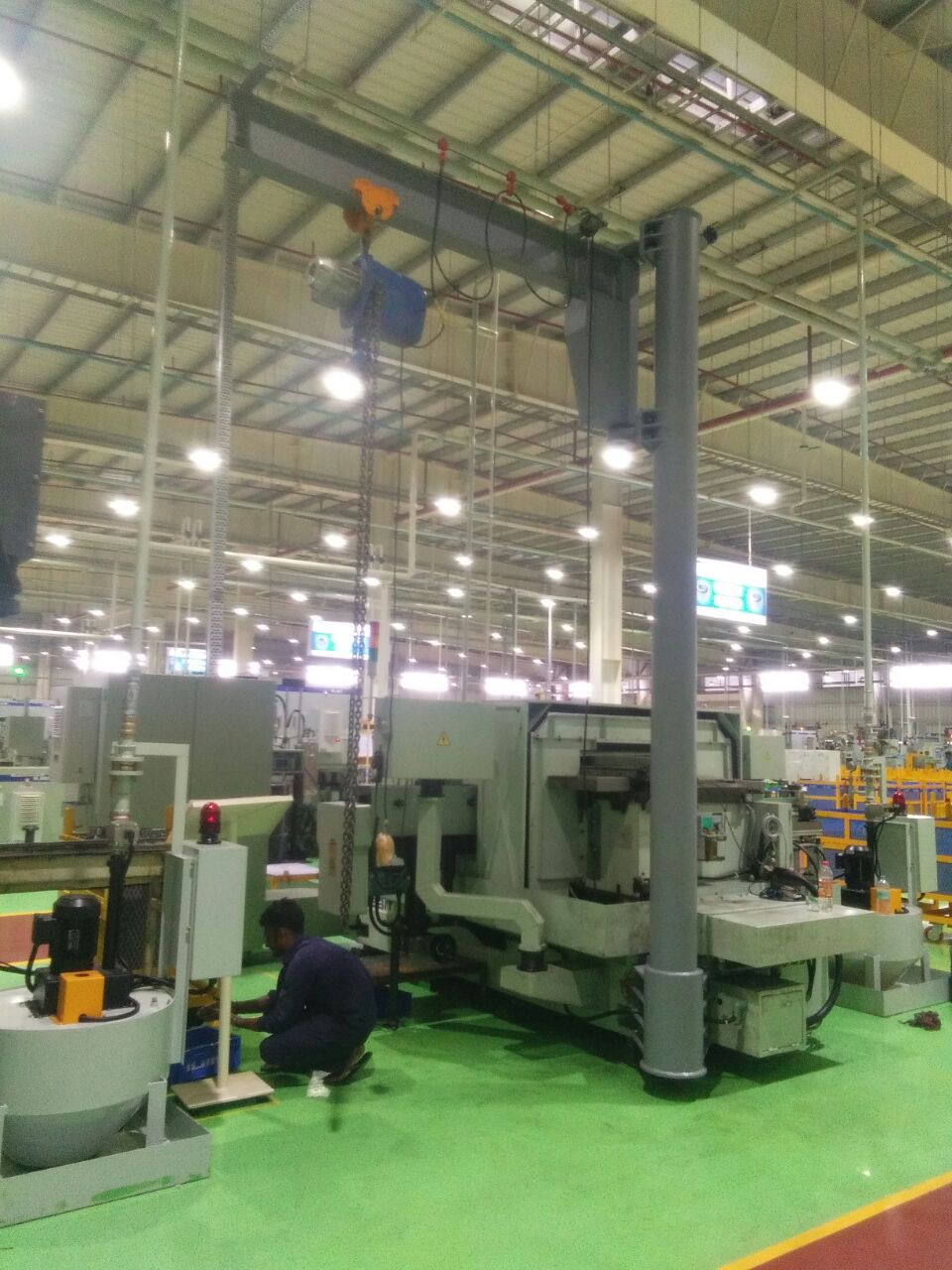 | Automation SPM Automated Pick Up & Drop System Pickup & Drop System – Industrial Automation Solution System Description: A custom-built automated system designed to pick components from a defined... View product → |
Frequently asked questions
How does an SPM identify a pick-and-place transfer failure?
The controller compares the component’s last confirmed location with gripper, presence, position, and destination signals. It flags failed pickup, partial pickup, dropped component, failed release, incorrect placement, blocked destination, transfer timeout, or contradictory sensor signals.
What happens immediately after the system detects a failed transfer?
The SPM records the fault, stops or holds the affected sequence, prevents unsafe downstream motion, and alerts the operator. The cell retains the failure state so the component location and machine condition can be checked before recovery.
When will automated pick up drop recovery retry, divert, or stop?
Retry applies only when sensors confirm a controlled recovery path and the workpiece remains identifiable. Divert applies when the component is recoverable but unsuitable for the normal destination. Stop applies when the location is unknown, sensors disagree, access is unsafe, or another collision could occur.
What must the operator do before resetting and restarting the cell?
Follow the cell’s safety procedure, isolate energy when required, inspect the gripper and transfer path, locate the component, clear the destination, and verify sensor and guarding status. Reset only after removing debris or damaged parts and confirming the restart position.
Which recovery features should you specify when evaluating an SPM?
Specify component-presence sensing, gripper confirmation, destination verification, timeout alarms, fault-history logging, safe hold positions, controlled retry and divert routines, guarded access, manual jog limits, and a restart sequence that requires confirmed state.